WSPR-Project-09_2015
Hello QRP Fans,
Now we finally finished our WSPR (Weak Signal Propagation Reporter Network) transmitter which transmits with about 200mW on a multiband GP.
We are running with the call sign DL0IF. Our reached distance can be seen under the official homepage of WSPR. WSPR-HP
We are proud to say everything is running well, even the first results of the last few weeks are looking great. Wolfgang DH3WO was working on a hands-on sheet which informs you about issues which are not described well or which are not clearly listed. We will also give you an overview about the WSPR technical side and some simple optimization which are done by us.
Tips for the Assembly and Adjustment of the Ultimate 3S and its Submodules
I recommend to install all optional resistors (R3=100k, R4=220k , R2=180 Ohms).
The circuit diagram shows 270 Ohms and a jumper A1-A2 for a fixed brightness reduction.. Jumper setting A0-A3 is instructed forthe software adjustable brightness. But you can also use the setting A2-A3 which allows a software adjustable brightness setting which is now limited by R2. Further on I propose to use 2.54 mm single row pinhead jumpers instead of the installation of soldered-in jumpers. Then you can make changes “on the spot” just by changing the related jumpers. (No risk to destroy the board).
Push buttons: I used 0,1uF ceramic capacitors across the push-buttons (Menu, Edit) against contact bouncing. Without them the contacts were too sensitive and you skipped the next editing position very often. You can also install a suitable 2×5 multipin connector for the programming interface. Feed in the supply voltage at +5V and ground as indicated. The connection to +PA can be made by a pinhead jumper between the rear pins. I also replaced all soldered output selection jumpers with 3 pin pinhead on the relay board of the low pass filter kit. Optional Out 1-5 antenna output selection. These jumpers are still easily accessible when all relays are built in. 2 pin pinheads were also used for the RF outputs 1-5 in case you want to connect separate antennas. You can use suitable connectors for the outputs in this case or you can easily solder a thin coaxial cable directly to the pins without the danger of destroying the relay board.
Adjustment of the output power (200mW= +23 dBm at 10 MHz) ( info: 250mW = +24 dBm)
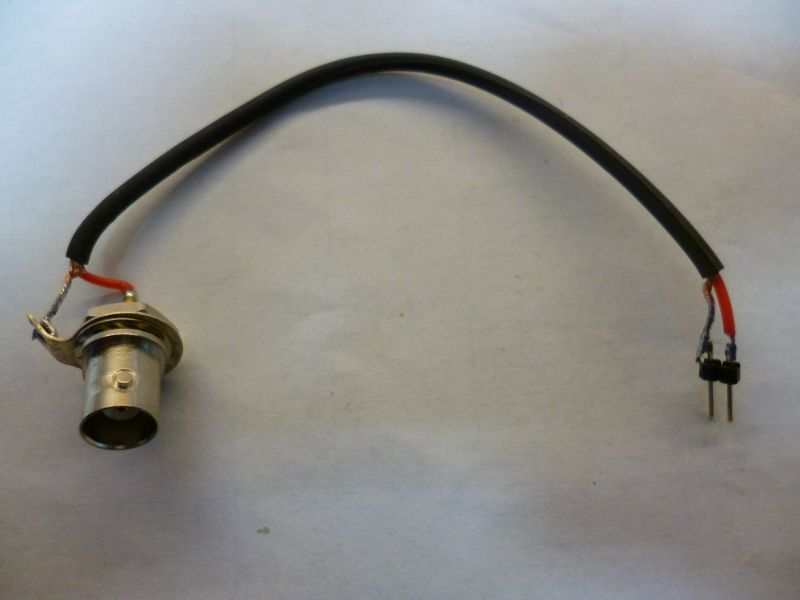
It is best to adjust the output directly at the main board of the Ultimate3S. If you do not want to solder a coaxial cable directly to the output you can use a sort cable which fits directly into the output RF+GND going to the relay board.(5×2 multipin connector). (See pictures, TestcableRFOutProcessorBoard.JPG)
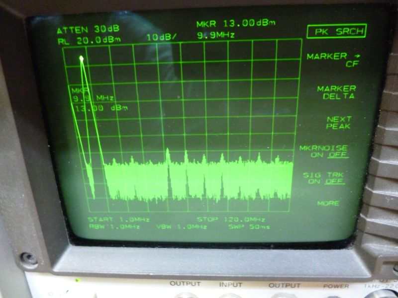
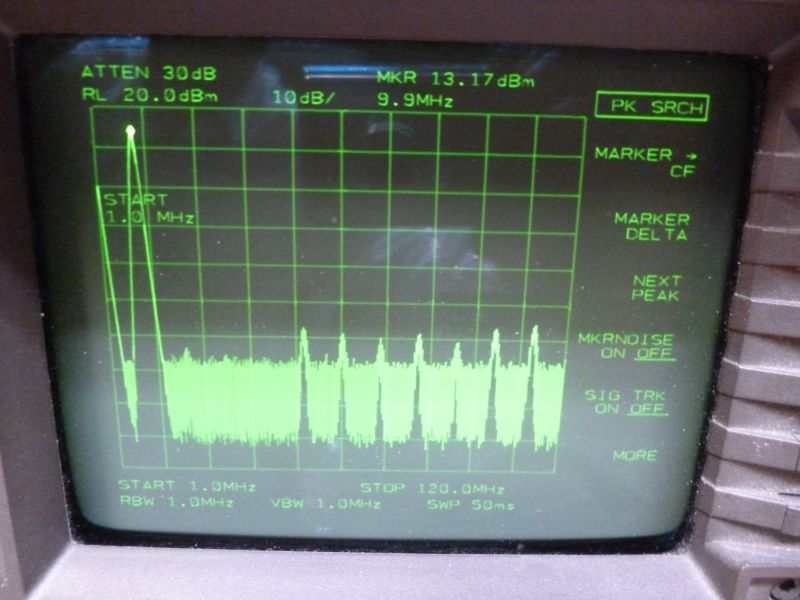
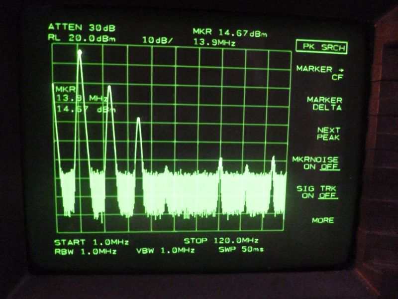
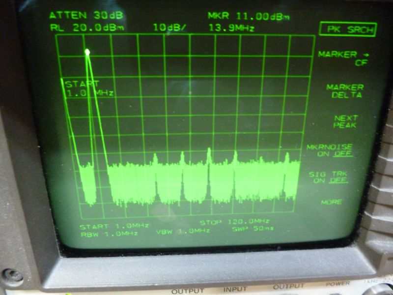
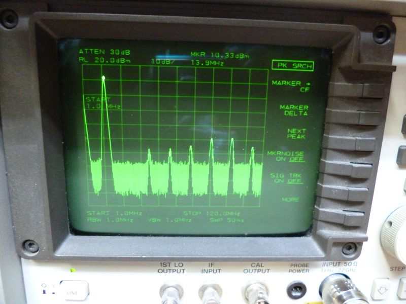
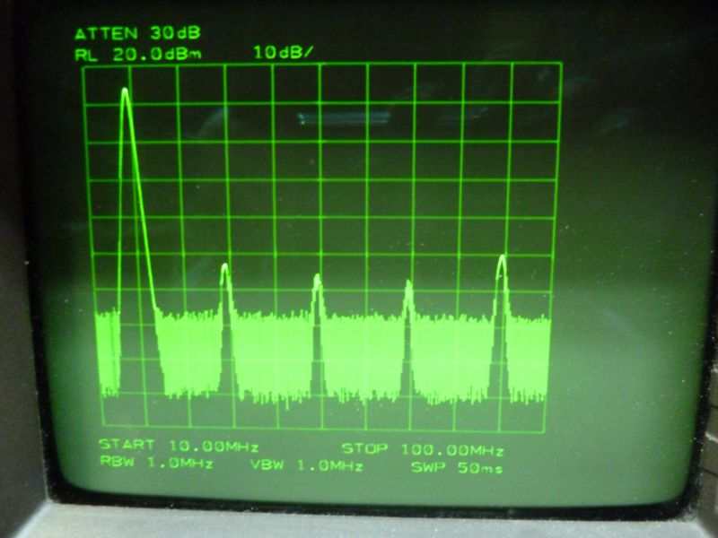
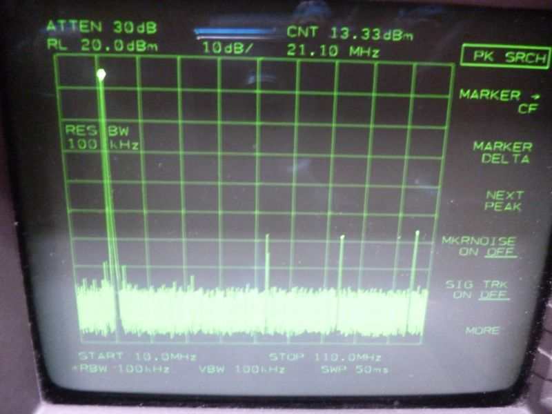
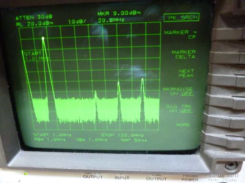
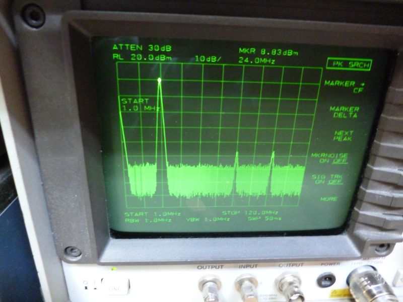
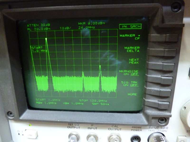
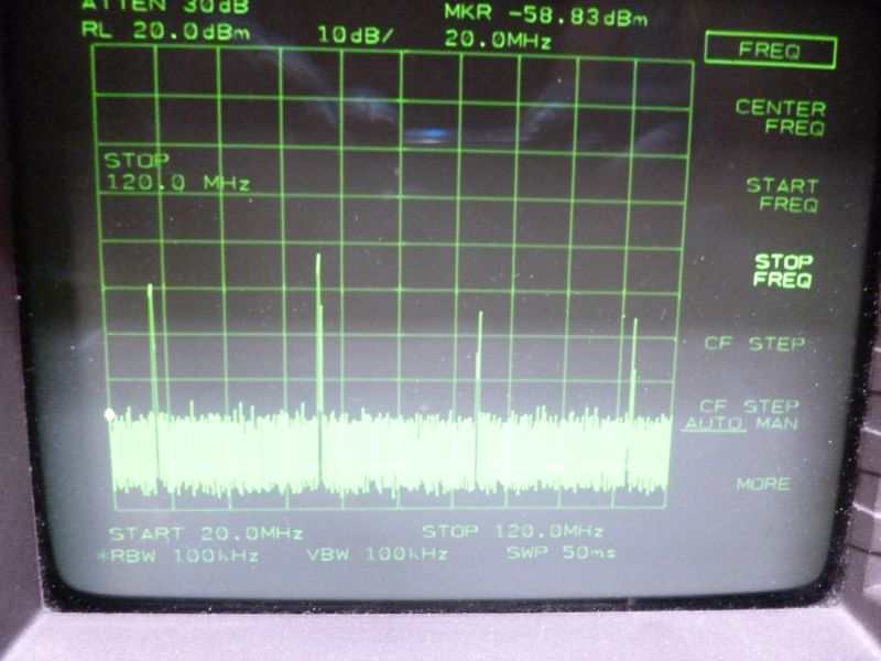
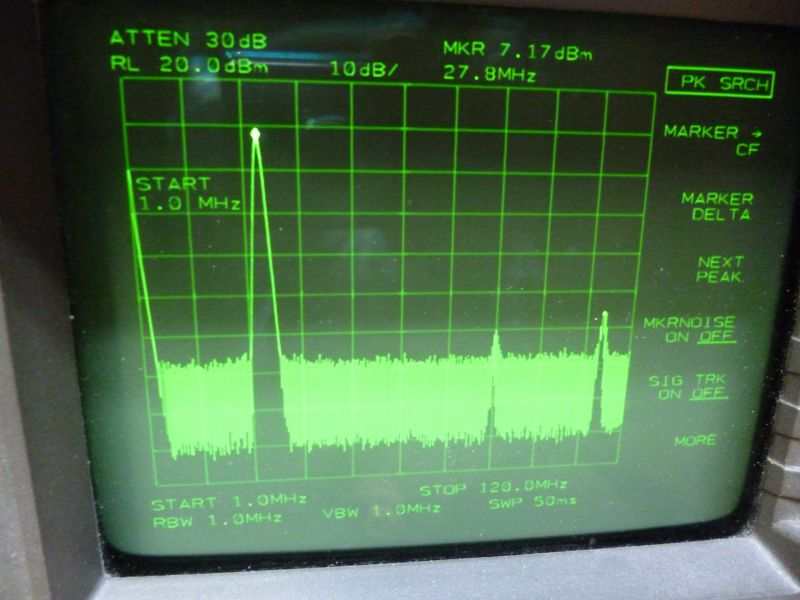
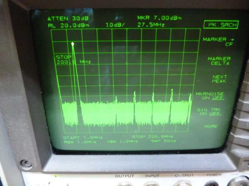
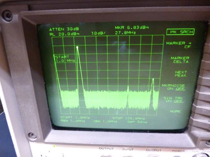
Install the 10 MHz low pass filter directly on the main board. Adjust the output power with R5 (4k7) carefully and check with the power meter. If you use a power sensor, e. g. HP8481A, install a pre-attenuator of 10 dB. This protects your powers sensor (max. 300 mW allowed) and your spectrum analyzer input. After power adjustment you can connect a spectrum analyzer to check the signal purity and harmonics. Then you can check all other low pass filters one by one by exchange on the main board and going to the related frequency. Do NOT re-adjust the power on the higher bands! Check only the power, signal purity and harmonics. Install the 30 m filter (relay 0) on the main boards and all others (20 – 10 m, relay 1-5) on the relay board. Put the relayboard in place. Re-check the output power and signal purity for all bands. The output power is about 0.5 dB lower compared to the single band version (loss in the low pass filter) and you will see the harmonics higher due to the crosstalk of the relay board. If you have a too high output power (in my case +25 dBm at 10 MHz) the higher bands will get worse and in my case the 28 MHz value had nearly no output power and the harmonics nearly no suppression. (56 MHz was even stronger than the wanted 28 MHz). If you compare a single band version (only one low pass filter used without the relay board) you will find a lower harmonics level than with all low pass filters installed and measuring at the output via the relay board, increasing at higher frequencies I measured an attenuation of about 0.5 dB for the relay board.
My measurements showed the following results:
|
Relay |
Band / Frequency |
Output dBm |
Spectrum via Relay Board +25dBm@10MHz (“over”) Picture No. |
Spectrum direct Single Band +13dBm@10MHz with single LPF Picture No. |
Spectrum via Relay Board +13dBm@10MHz full equipped Picture No. |
| 0 | 30m / 10MHz | 23.0 | 1 | 2 | 3 |
| 1 | 20m / 14MHz | 20.6 | 4 | 5 | 6 |
| 2 | 17m / 18MHz | 20.6 | 7 | 8 | 9 |
| 3 | 15m / 21MHz | 19.6 | 10 | 11 | 12 |
| 4 | 12m / 24MHz | 19.4 | 13 | 14 | 15 |
| 5 | 10m / 28MHz | 17.9 | 16 | 17a, 17b | 18a, 18b |
You can see the influence of a too high output power (about 25 dBm@10MHz) and compare the influence/cross talk of the relay board.
Compare the “over”-spectrum to the “23dBm”-spectrum. (Measured with the LPF –board as single board directly on the main controller board.)
Additionally you see the “cpl”-pictures which you get with a fully equipped Ultimate 3S (relay boards and all filter boards in place). You see the influence of the “crosstalk” when all LPF are in place and switched through step by step. (Relay 0 = 10 MHz … Relay 5 = 28 MHz).
These measurements were taken end of September 2015 at the Ultimate 3S running at our station DR2W (DL0IF).
In the meantime there was a more detailed investigation by Hans Summers (G0UPL) about the spectrum purity and drain current for different output power levels. You can find this on the homepage of QRP Labs.
The use of the 2.54 mm pinheads is also very advisable for the GPS receiver kit QLG1 as you can easily use the suitable female terminal strips for the cable connection between the GPS module and the Ultimate 3S. If you want to solder in the cable ends directly it is easier because you do not have to solder at the board during rearrangement of the cabling.
Use a suitable socket for IC1 (74ACT08). This makes a replacement easier.
Power Supply: with a solar panel, solar regulator and 12 V PB-gel-battery (12V/12Ah).
The station is powered from a 12V/12Ah battery and recharged from solar panel and external charge regulator. (Do not forget the correct fuses directly at the battery and about M0.3A or less for the Ultimate 3S. A reverse polarity protection with a diode in the Ultimate 3S is advisable.)
The 12V DC voltage is regulated down to 5V DC by a high quality switching regulator (e. g. Recom R78E5,0-0,5) in the standard application but with additional 100 uF/25V electrolytic capacitors at the input and output side. (A 7805 linear regulator replacement. Advantage: an output current of about 0.12 A needs an input current of max. 50%! (So less than 60 mA needed during transmission if one BS170 is in use.)
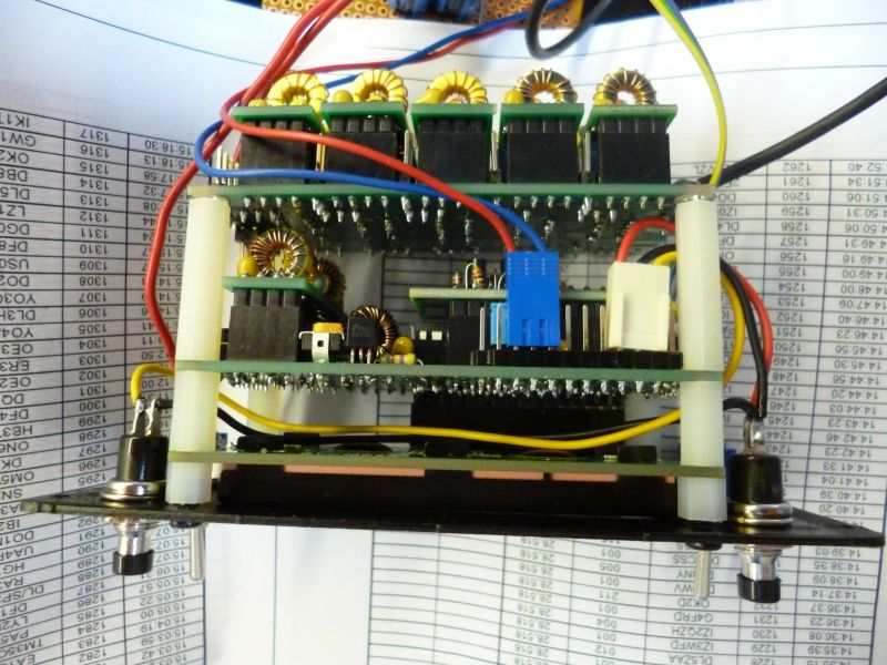
We did not have any problems with this supply. All fits into the standard case delivered for the Ultimate 3S and has a lower heat dissipation. The wiring was done on a piece of “Veroboard” in conventional wiring.
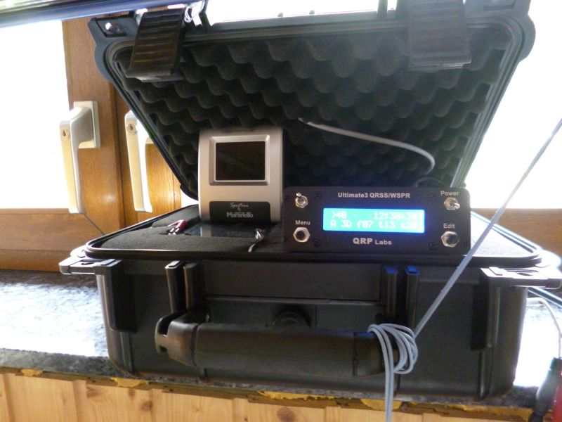
Installation on site: The whole station is inside the “pelicase” box. You can see the grey cable to the GPS antenna at the lid of the pelicase, the 12V battery on the left and the Ultimate3S on the right which fits also into its appropriate place. (The DCF clock on the left was only put in to keep the lid open and has no further use) ! The antenna cable and the DC cable from the solar charging regulator are fed through tight bushings at the right to avoid environmental influences.
I hope you got a short impression for your own project but please understand that this info is given without warranty from our side. Good luck with your project!
Wolfgang DH3WO (@dr2w)